:strip_icc():strip_exif()/Bronzeshop/PG-01-Mehrstoffzinnbronzen.jpg)
:strip_icc():strip_exif()/Bronzeshop/PG-02-Zinnbronzen.jpg)
:strip_icc():strip_exif()/Bronzeshop/PG-03-Aluminiumbronzen.jpg)
:strip_icc():strip_exif()/Bronzeshop/PG-04-Bleibronzen.jpg)
:strip_icc():strip_exif()/Bronzeshop/PG-05-Sondermessing.jpg)
:strip_icc():strip_exif()/Bronzeshop/PG-06-Metafram.jpg)
:strip_icc():strip_exif()/Bronzeshop/PG-07-Wieland-B09.jpg)
:strip_icc():strip_exif()/Bronzeshop/PG-09-Looser-Gleitlager-LG41.jpg)
:strip_icc():strip_exif()/Bronzeshop/PG-10-Permaglide.jpg)
:strip_icc():strip_exif()/Bronzeshop/form-rundrohr-3d.png)
:strip_icc():strip_exif()/Bronzeshop/form-rund-3d.png)
:strip_icc():strip_exif()/Bronzeshop/form-vierkant-3d.png)
:strip_icc():strip_exif()/Bronzeshop/form-flach-3d.png)
:strip_icc():strip_exif()/Bronzeshop/form-sechskant-3d.png)
Wieland-B09
Table of contents
- Wieland-B09
- Material descriptions
- Physical properties (Guideline values)
- Strenght properties (Guideline values)
- Allowable loading capacity of bearings
- Installation tolerances
- Bearings with lubrication indents
- Bearings with hole pattern
- Bearing clearance and shaft tolerance
- Fitting and lubricating the bushes with seal
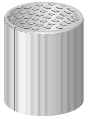
Wieland-B09
The rolled Wieland-B09 bushings are made from a CuSn8 wrought material and can absorb very high loads despite their thin walls. This is why these bearings are particularly suitable for oscillating bearings (oscillating movement), the most common application for rolled Wieland bushes. The outstanding tin bronze material gives the bushes excellent sliding properties and high wear resistance. Rolled Wieland bushes are available in standardized dimensions with lubrication pockets. This type of bushing has the advantage that it can be cut to any desired length. We also offer custom-made products and sizes according to your specifications.
Material descriptions
Wieland-B09 is a tin bronze with excellent sliding properties. The material is particularly suitable when high wear resistance, corrosion resistance and fatigue strength are required. Due to the thin walls of rolled bushes, they can absorb very high specific forces. These may be higher than with the relatively thick-walled turned bushes. Very high loads are possible, especially with oscillating bearings (oscillating movement).
|
Material designation: CuSn8P DIN ISO 4382-2 |
Composition (approximate mass fraction): Cu 91.3%, Sn 8.5%, P 0.2% |
Physical properties (Guideline values)
| Specific gravity: 8,8 kg/dm3 |
Coefficient of thermal expansion (20 – 300°C): 18,5 10-6/K |
| Thermal conductivity: 60 W/mK | Modulus of elasticity (20°C): 115 kN/mm2 |
Strenght properties (Guideline values)
| Hardness: 125 HB |
Tensile strength Rm; 470 N/mm2 |
| 0,2%-Yield point Rpp0,2: 300 N/mm2 | Elongation at fracture A: 40 % |
Permissible load capacity of plain bearings
Rotating shaft > 2 m/s: 40 N/mm2
General properties
The characteristic feature of rolled boxes is their thinness. For this reason, the space required for bearings with the same shaft diameter and the same load spectrum is smaller than for turned bushings or even roller bearings. The larger the shaft diameter, the more important this is. Rolled bushes can be supplied with or without a flange.
Advantages:
- Fully recyclable
- more cost-effective than turned bushes
- minimal space requirement
- Weight saving compared to turned bushings or roller bearings
- High load capacity, therefore particularly suitable for oscillating bearings
- Grooves are tested
- Grease reservoirs for long-term lubrication possible
How to use
Highly resilient bronze with very good heat resistance, very good corrosion resistance, wear-resistant. Hardened shafts required for high loads
Application: Spherical plain bearings for shock and impact loads, bearings in hydraulic cylinders, bearings in the arms of excavator joints and in agricultural machinery.
For flanged bushings, the following must also be considered:
- Radial and axial forces are absorbed by a bushing
- Instead of thrust washer and cylindrical bushing, only one bearing element
- High dimensional stability; fixing operation no longer required, e.g. for thrust washers
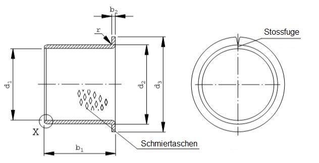
Dimensional tolerances
Cylinder sleeves with lubrication pockets ST
 |
|
|
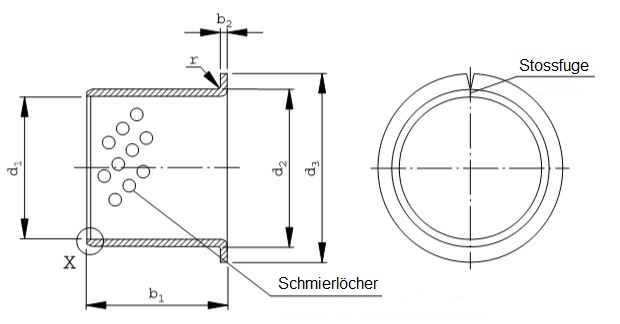
Cylinder sleeves perforated LD
 |
 |
Cylinder sleeves perforated LD with seal
 |
 |
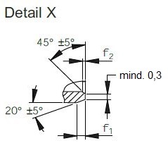
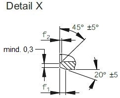
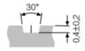
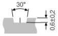
External and internal chamfers
s* f1 f2
1 0.6 ± 0.4 max. 0.4**
1.5 0.6 ± 0.4 0.4 ± 0.3**
2 1.2 ± 0.4 0.4 ± 0.3
2.5 1.8 ± 0.6 0.6 ± 0.4
* s = b2 = (d2 – d1) / 2
** optionally rounded
|
|
Flange sleeves with smear pockets ST
 |
 |
|
Flange perforated LD
 |
|
Installation tolerances
| Nominal dimension d1 | Installation tolerance | ||
| bigger than | till | Housing H7 | Bearing inside-Ø after mounting into housing H7 (middle) |
| 10 | 18 | 0 / +0,018 | 0 / +0,043 |
| 18 | 30 | 0 / +0,021 | 0 / +0,052 |
| 30 | 50 | 0 / +0,025 | 0 / +0,062 |
| 50 | 80 | 0 / +0,030 | 0 / +0,074 |
| 80 | 120 | 0 / +0,035 | 0 / +0,087 |
| 120 | 180 | 0 / +0,040 | 0 / +0,100 |
| 180 | 250 | 0 / +0,046 | 0 / +0,115 |
| 250 | 305 | 0 / +0,052 | 0 / +0,130 |
Check according to DIN 1494/ISO 3547 part 2
Flange diameter [d3] is defined in accordance with DIN ISO 2768 with rough
Width tolerance for cylindrical and flanged bearings
Width [b1] till outside diameters [d2] 100 mm: ±0,25 mm
Width [b1] bigger than outside diameters [d2] 100 mm: ±0,5 mm
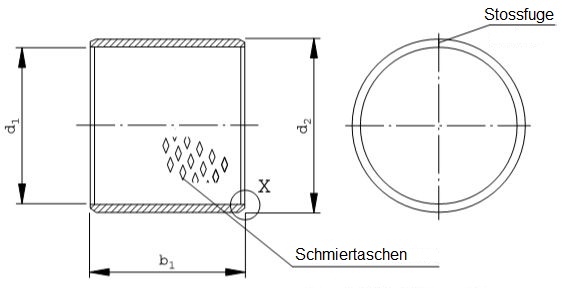
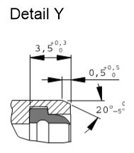
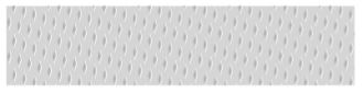
Bushings with lubrication grooves
Bushings with lubrication pockets are sliding elements that have been tried and tested for years. The lubrication pockets, which are already rolled into the shaft, are evenly distributed over the entire running surface. Filled with grease before mounting the shaft, they help the bearing point to achieve an even film of grease over the entire bearing point.
|
Lubrication pocket no. 3 – Carrying capacity approx. 75%
Rhombus shape for bushes &üchsen Ø ≤ 16 mm, DIN 1494/ISO 3547, Part 3, Version N2
|
Lubricating pocket no. 4 – load-bearing capacity approx. 78%
|
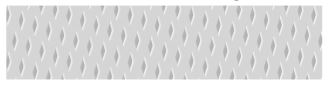
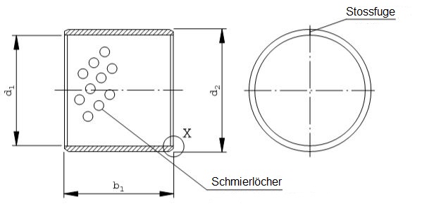
Perforated bushings
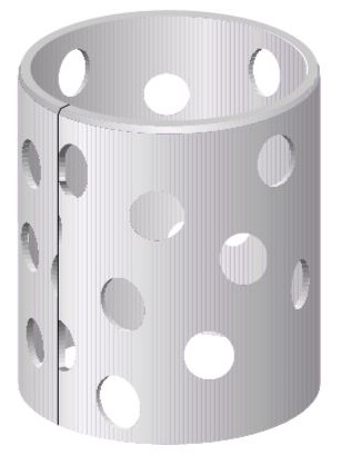
The perforated bushings are a further development of the bushings with lubricating pockets. They are provided with
a precisely defined hole pattern that is filled with grease or a paste and has the following
advantages:
- the running time is extended
- the greasing interval is increased
- dirt and abrasion are collected in the bearings and
- the wear behavior is significantly improved
With these bushings
- Choose bold or paste individually
- Customize the storage conditions and
- the storage material is recycled
Cutting the standard bushes to intermediate widths is only recommended to a limited extent, as the sheets are cut to size, resulting in sharp edges. Bushings with deviating width dimensions should therefore be remade.
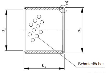
Bushings with seal
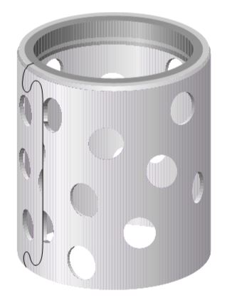
In contrast to the familiar plain bearing designs, where the bushing and seal have to be installed separately.
It is also possible to purchase the bushing and seal as a complete part.
The bearing with seal has the following advantages:
- The running time is significantly extended:
– optimum lubrication, as the bearing point is filled first before the grease escapes via the seal
– protection against the ingress of moisture and foreign bodies of all kinds - In contrast to the usual seals, minimal space requirement
- Seals and plain bearings 100% recyclable
- Only one complete part is ordered and assembled, no different individual parts – warehousing is also simplified
Properties of the seal:
- Very good flexibility over a wide temperature range in combination with maximum sealing effect and high abrasion resistance
- No running of the sealing lip into the shaft
- linear support even under load and edge pressure
- Excellent resistance to grease, oils and hydraulic fluids
- High resistance to UV light and ageing of the material
Materials and surface finishes
The surface hardness of the shafts should preferably be greater than 50 HRC. Alloyed steels or steels with
appropriate surface treatment are therefore particularly recommended. Hard chrome-plated shafts have also proven themselves well, but the chrome layer should be kept as thin as possible. The shafts should be ground to Rz values between 1 and 4 μm. If these roughness values cannot be achieved,
additional polishing or «honing» of the shaft is recommended in order to break the roughness peaks and increase the contact ratio.
Drawn shafts have also proven their worth, especially for axial movements.
Lubricants
- lithium-saponified grease for standard bearings
- lithium-saponified grease with additives for higher demands
- Pastes for long-term lubrication
- Öl for closed systems
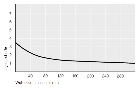
Bearing clearance and shaft tolerance
The required average bearing clearance depends on the intended lubrication, the load and the sliding speed.
The diagram is intended to make it easier to select the required clearance. The curve is designed for general mechanical engineering. For bearing arrangements in rough operation, the curve can be slightly stepped upwards.
The tolerance position of the shaft must be defined according to the desired minimum clearance. The tolerance class should be IT6 for high requirements and IT7 or IT8 in normal cases
| Situation | Camp game |
| Lubrication status: Grease | > 0.1 mm |
| Lubrication status: Öl | small |
| Load: large | small |
| Burden: small | large |
| Movement: slow | small |
| Movement: oscillating | small |
| movement: fast | large |
If standard shafts with an inner diameter tolerance of H9 are used, it is recommended that the shaft is toleranced with e or f. For shafts with an h tolerance, the housing bore can be extended from H7 to F7, provided the bearing load is not too high.
The bushing adapts to the respective housing and the bushing bore becomes slightly larger. Bearing clearances that are too small can thus be avoided.Construction notesHow to use and use
The mounting hole in the housing is preferably designed with a tolerance of H7. After being pressed into this bore, the inner diameter of the bushing generally has a tolerance of H9 in the standard version. If other tolerances are required, please contact us.
Rolled bushes can bounce slightly at the butt joint when not installed, but this has no effect on the mass or the tight fit when installed. The bushes, like turned ones, have a press-fit dimension.
When the bushes are pressed in, the joint closes and the butt joint surfaces sit firmly and form-fittingly on top of each other so that the press-fit dimension can take effect. The bushing adapts to the casing and thus acquires its final shape.To make it easier to fit the bushing, the housing should have a chamfer of between 15 and 45 degrees (flanged bushings 45 degrees). In the case of flanged bushes, it is also important to ensure that the chamfer in the housing is matched to the radius between the bushing shaft and the flange. The radius R corresponds to the bushing wall thickness, at least 2 mm.
Shoulder spine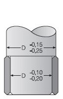
Bushing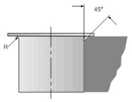
Fitting and lubricating the bushes with seal
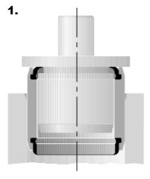
1. Pressing in the bushing
The bushing is pressed in with the seals fitted. For error-free installation, a shoulder mandrel is recommended that has a free rotation for the sealing lip between the guide shaft and shoulder. The free rotation is necessary so that the seal is not damaged when it is pressed in. The shoulder mandrel should have a slip chamfer of at least 3 mm x 15°. However, the bushing can also be pressed in with a plate. The seal is pressed elastically towards the center of the bushing and returns to its original position after the press-fit process.
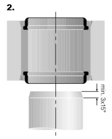
2. Mounting the shaft
When mounting the shaft, please note that the inner diameter of the sealing lip has a smaller diameter than the shaft. The shaft should therefore have a chamfer of at least 3 mm x 15° so that it can be inserted easily. Assembly is further simplified if the shaft is lightly greased before insertion.
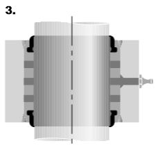
3. Lubricating the bushing
Without a seal, complete filling of the bearing via the grease nipple is not guaranteed. Grease quickly escapes from the unloaded area, while the loaded area remains unfilled. A throttle pressure is built up in the bearing by the seal during lubrication, as a result of which the grease only escapes via the seal once the bushing is completely filled. If the bushing cannot be lubricated via a grease nipple, ensure that the bushing is well greased before mounting the shaft.
We will be happy to advise you.
Technical specifications are subject to change without notice.